
1. Features:
- Compliant IEEE802.3af/at PD interface
- Small SIL package size – 56.2mm (L) x 25mm (H)
- Input voltage range 40V to 57V
- Minimal (low cost) external components required
- Short-circuit protection
- 1500V isolation (input to output)
2. Description:
The PD-1003 module is designed to extract power from a conventional twice pair 1000M Ethernet or single pair 10/100M Ethernet cable. Let customer easily and flexible building in product design. This designed can provide total power up to 30W as specified by the POE plus IEEE802.3at standard. In addition, The PD-1003 module can be interfaced to any PSE that follow detection and classification procedures defined by the IEEE802.3af/at standard.
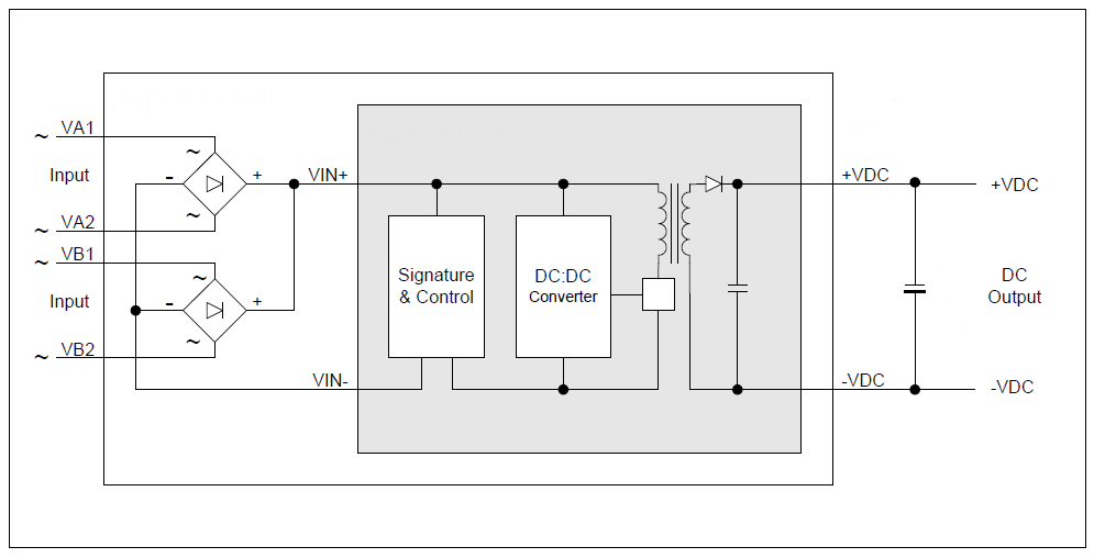
3. PD-1003 Block Diagram:
4. PD-1003 Package Format:
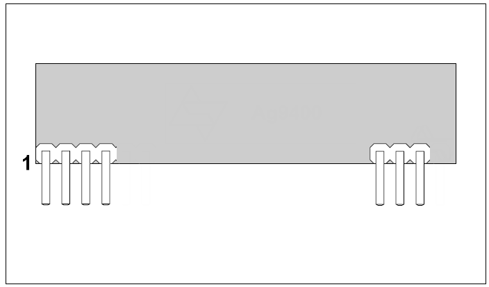
5. Pin Description:
| Pin No. | Name | Description |
| 1 | VA1 | RX Input (1). This input pin is used in conjunction with VA2 and connects to the centre tap of the transformer connected to pins 1 & 2 of the RJ45 connector (RX) - it is not polarity sensitive. |
| 2 | VA2 | TX Input (2). This input pin is used in conjunction with VA1 and connects to the centre tap of the transformer connected to pins 3 & 6 of the RJ45 connector (TX) - it is not polarity sensitive. |
| 3 | VB1 | Direct Input (1). This input pin is used in conjunction with VB2 and connects to pin 4 & 5 of the RJ45 connector - it is not polarity sensitive. |
| 4 | VB2 | Direct Input (2). This input pin is used in conjunction with VB1 and connects to pin 7 & 8 of the RJ45 connector - it is not polarity sensitive. |
| 5 | -VDC | DC Return. This pin is the return path for the +VDC output. |
| 6 | +VDC | DC Output. This pin provides the regulated output ofrom the DC/DC converter. |
| 7 | PSE detect | Detect PSE is Type1 or Type2 |
*Option: standard module doesn’t have this PIN, only add by required
6. Typical System Diagram:
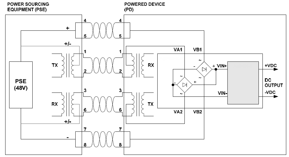
6.1 PD Signature
When the PD-1003 is connected to the Cat 5e cable, it will automatically present a Powered Device (PD) signature to the Power Sourcing Equipment (PSE), when requested. The equipment will then recognize that a powered device is connected to that line and supply power.
6.2 Isolation
To meet the safety isolation requirements of IEEE802.3af/at section 33.4.1 a Powered Device (PD) must pass the electrical strength test of IEC 60950 sub clause6.2. This calls for either a) 1500Vac test or b) 1500V impulse test. The PD-1003 is specified to meet the 1500Vdc impulse test. It is also important that the tracks on either side of the isolation barrier have at least a 3mm clearance.
6.3 DC/DC Converter The PD-1003’s DC/DC converter provides a regulated low rip
7. Typical Application:
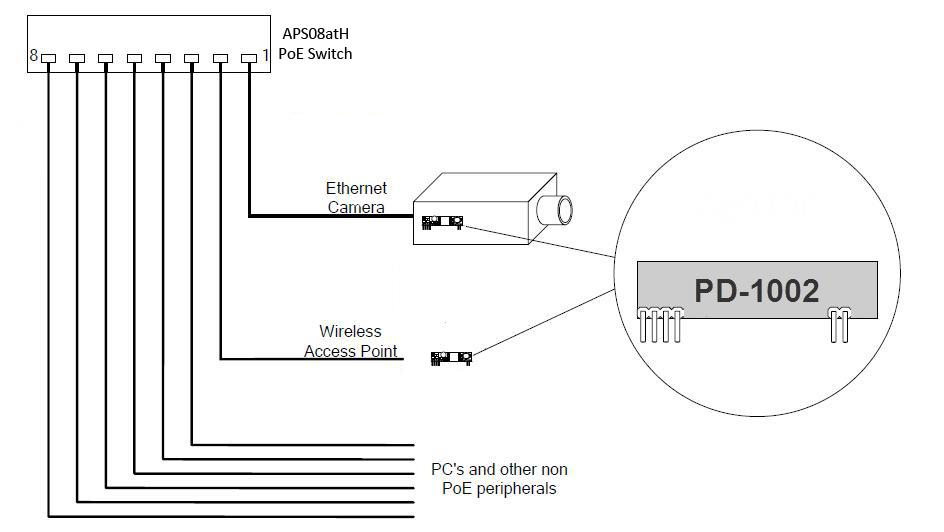
The PD-1003 can be used in numerous applications, in the example shown in Figure above, the data+power outputs from the PoE switch are connected to the each output that supports Power over Ethernet (PoE). In this example port 1 is connected to an ethernet camera and port 2 is connected to a wireless access point, both of these devices have a built-in PD-1003. When the PoE Switch is switched on (or when the device is connected), the PoE Switch will check each output for a PoE signature. On ports 1 and 2 the PD-1003 will identify themselves as PoE enabled devices and will supply both data and power to these peripherals. The other ports (shown in this example) will not have a PoE signature and only pass the data through to these peripherals. The PoE Switch will continuously monitor each output to see if a PoE enabled device has been added or removed
8. Operating Temperature Range:
Because the PD-1003 is a power component, it will generate heat, so it is
important that this be taken into consideration at the design stage. The heart of
the PD-1003 is a DC/DC converter, which like any other power supply will generate
heat. The amount of heat generated by the module will depend on the load it is
required to drive and the input voltage supplied by the PSE. The PD-1003 has a
maximum ambient operating temperature of 70°C. These results are in still air
without any heat sinking. The output stage of the PD-1003 has no built-in thermal
protection, to prevent the module from being damaged it is recommended that the
module be powered by an IEEE 802.3af/at compliant PSE or PoE Switch equipment.
However the PD-1003 may be powered by a user designed power supply which
should include thermal and over current protection.
Because each application is different it is impossible to give fixed and absolute thermal recommendations.
10. Electrical Characteristics:
10.1 Absolute Maximum Ratings
| Parameter | Symbol | Min | Max | Units | |
| 1 | DC Supply Voltage | Vcc | -0.3 | 60 | V |
| 2 | DC Supply Voltage Surge for 1ms | Vsurge | -0.6 | 80 | V |
| 3 | Storage Temperature | Ts | -40 | +100 | °C |
10.2 Recommended Operating Conditions
| Parameeter | Symbol | Min | Typ | Max | Units | |
| 1 | input Supply Voltage | Vin | 40 | 48 | 57 | V |
| 2 | Under Voltage Lockout (After start up) | Vlock | 33 | 36 | V | |
| 3 | Operating Temperature | Top | -20 | 25 | 70 | °C |
10.3 DC Electrical Characteristics
| DC Characteristic | Sym | Min | Typ | Max | Units | Remark | |
| 1 | Nominal Output Voltage | +VDC | 11.5 | 12.2 | 12.7 | V | |
| 2 | Output Current(VIN=48V) | PWR | 2.5 | A | |||
| 3 | Output Power | PWR | 30 | W | @70°C | ||
| Output Power | PWR | 33 | W | @25°C | |||
| 4 | Peak to Peak ripple noise | Vp-p | 200 | mVp-p | @Max load | ||
| 5 | Steady state Effciency | EFF | 83.5 | % | @1A | ||
| Steady state Effciency | EFF | 87.5 | % | @1.5A | |||
| Steady state Effciency | EFF | 88.5 | % | @2.5A | |||
| 6 | Static load regulation | Static | 100 | mV | |||
| 7 | Dymamic load regulation | Dynamic | 120 | mV | Dynamic load 0 ~ 2.5A (Note 4) | ||
| 8 | lsolation Voltage(I/O) | Viso | 1500 | Vpk | Impulse Test |
| Note | 1: Typical figures are at 25°C with a nominal 48V supply and are for design aid only. Not Guaranteed2: The output ripple and noise can be reduced with an external filter.3: Continuous short circuit duration is applicable at 25'C ambient temperature infree air. At higher temperatures or with restricted airflow (e.g. in a sealedenclosure) the duration will need to be limited to avoid overheating.4. The load current is variate between 0 and 2.5A (full-load) during dynamic test.The average of load current for dynamic test is half of full-load. |
Related Products


AOPS04G
$0.00


APS104G-EX_PoE
$0.00


PSE-1000GU
$0.00


APOE48V-1G
$0.00


APOE48V-2.5G
$0.00


APOE2410G
$0.00


APOE3005G
$0.00


APOE2405
$0.00
Recently Viewed Products
Sleeve High Neck Bodycon Dress
$132.00
Lorem ipsum dolor sit amet, consectetur adipiscing elit. Nam fringilla augue nec est tristique auctor. Donec non est at libero.